28.02.2023
What are repeaters used for? GSM repeaters as a major headache for mobile operators
Nowadays, everyone is familiar with the situation when the Wi-Fi signal is weak or completely absent in some part of the room; one wants universal and high-quality Internet. How to do this? This is where a repeater router comes in to support.
What it is? How does it work? What are the types of systems, principles of their operation and installation? Answers to these questions and many more useful information you will find here.
Most likely, absolutely everyone knows that sometimes in the farthest corner of the house it is impossible to connect to the home network - the signal is so bad.
Or, if a certain number of people use the home network, which causes the download rate to drop significantly.
You should not count on the fact that when installing a router, the repeater will strengthen the initially weak signal. It is designed to distribute the signal from the point where there is a good Internet connection to places with lower speed.
Another practical note: based on the fact that a repeater is often called an amplifier, an opinion is formed about its function of increasing power and signal propagation.
But the WiFi repeater does not increase the working signal in any way, but only expands it to the space corresponding to the settings.
In other words, purchasing a repeater will not increase anything at all and will in no way make your Internet network superfast, but rather, on the contrary, it will slow down the pace a little due to the formation of another signal distribution point.
However, this should not scare you - we will analyze the impact of the repeater on the tempo further and explain in what moments it will be insignificant.
It is rational to use a repeater in such cases, if you need to establish a stable connection in an area where there is poor reception (an agricultural area or an impressive distance in a populated area).
How do you know if you need a repeater?
First of all, before you go to purchase a repeater, think about the fact that perhaps there is another solution to the issue.
We are talking here not about the previously listed increase in signal strength, but trivially about what space in the area is allocated to the router.
The closer to the middle of the space, from a geometric point of view, your device is, the more measured the signal transmission will be to all corners of the house without exception.
Also, find out where the antenna is pointing. In order to distribute the signal horizontally, it should be installed with the end up, that is, vertically.
What's going on with the Internet speed?
In some cases, doubts may arise regarding the need to purchase a repeater.
The most common reason is related to the signal propagation distance. It seems to potential users that the signal is strengthening, but the Internet speed is decreasing.
Practical use of repeaters shows that changes in speed indicators do occur. This is due to the fact that each subsequent element participating in one way or another in the distribution of the Internet has an impact on the network slowdown.
But the speed reduction is usually not that significant. The degree of perceptible influence on the speed of signal transmission is determined by the technical data of the devices in the chain.
We can say that the network will not “glitch” and “slow down” in any way if your devices pick up the network uninterruptedly from the very beginning.
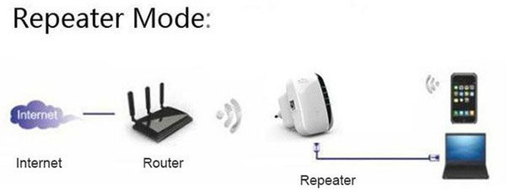
Router as a replacement for a repeater
There are common opinions that if you have an extra but functioning router at home, then it is absolutely not necessary to buy a Wi-Fi signal repeater.
Most models are designed in such a way that they have repeater functions; the main thing is to configure them correctly.
This is a longer procedure than setting up an ordinary repeater, but it is quite possible to implement it on your own.
Note that it is generally easier to pair two devices from the same manufacturer because having the same functionality opens up more options.
The installation procedure itself, in turn, depends on the logo and brand name. This is very important to take into account, as well as reading the instructions before starting setup.
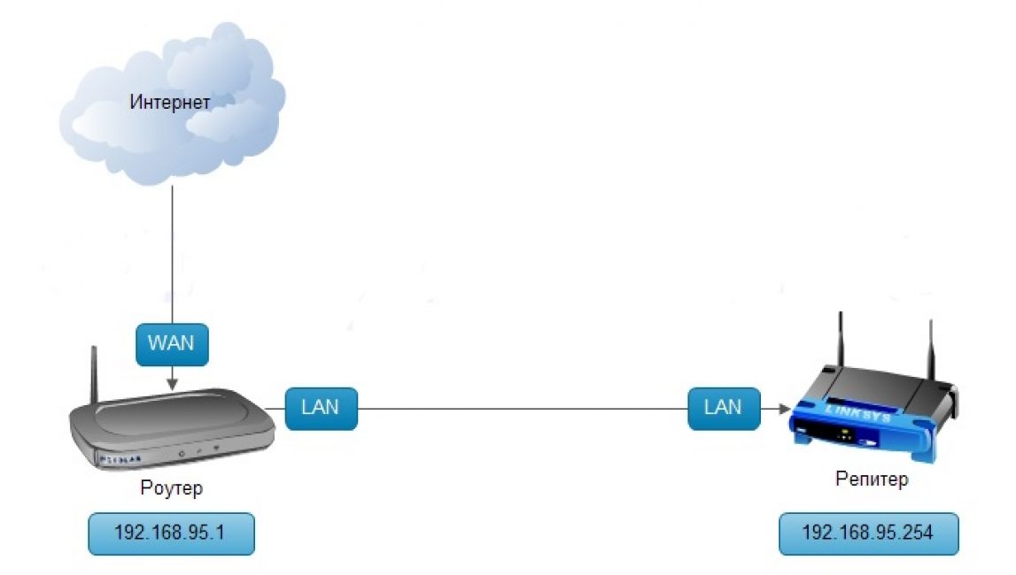
So, the router that you want to use as a Wi-Fi repeater should be connected to the PC using a special cable (wire).
The device must be set to an IP address of 192.168.1.21 with a subnet mask of 255.255.255.0.
Then, as when installing a repeater, you should enter the IP address from the bottom of the device into the address line. Re-use the standard login and password - admin/admin.
Then, as when installing a repeater, you should enter the IP address (located at the bottom of the device) in the address line.
Reapply the standard login and password - admin/admin. In the page that opens, you need to find the “Wireless Mode” tab and enter the settings.
Then, as when installing a repeater, you should enter the IP address (located at the bottom of the device) in the address line. Reapply the standard login and password - admin/admin.
In the page that opens, you need to find the “Wireless Mode” tab and enter the settings.
We are interested in the “Enable WDS” function – an assistant for organizing a network that will connect two routers.
In addition, you may need to change the IP location of the router, which will act as a repeater in order for you to be able to enter the settings system and make your necessary adjustments there.
It is permissible to simply replace the last numbers or add a zero after it.
What does the Wi-Fi repeater look like?
There are various modifications of repeaters. Various in volume and configuration, in some ways they resemble a charger for a smartphone, the only thing is that there is no cable.
So, the sample in the image looks like a small arc-shaped plate with a plug for installation in a socket, LED indicators, a network for an Ethernet cable and a reset key.
In addition, there are repeaters that have very minor differences in essence from a router.
As a rule, the delivery includes instructions, an Ethernet cable and a drive with drivers.
WPS key
The majority of current devices have a WPS key (or QSS in certain models); it was created to simplify the use of the device, however, in some cases it creates obstacles to network consumption.
If both the router and the repeater have this key, you will need to perform the following actions: first press it on the first device, and then on the other.
It takes a couple of minutes to detect, after such manipulations the repeater and router agree with each other, and voila - you are allowed to operate.
However, some users resort to advice that recommends installing the repeater manually, selecting a specific Wi-Fi network, in order, firstly, to reduce the number of interruptions in relaying, and secondly, to insure themselves.
The WPS technique is easily hackable. For this reason, it is often recommended to disable this system, if you do not need to repeatedly connect external devices.
It is also worth paying attention to the fact that in some cases the WPS key is equipped with a reset function.
Everything depends on the duration of the press: if you hold your finger on the button for a few seconds, then instead of connecting WPS, reboot the repeater, and all options without exception will return to their original positions (factory settings).
Installing a Wi-Fi repeater
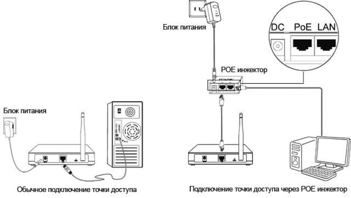
The wifi tp-link repeater connects to the computer using a special cable, the most popular among most users, called “twisted two”.
The repeater's power supply is connected via a POE thermal injector.
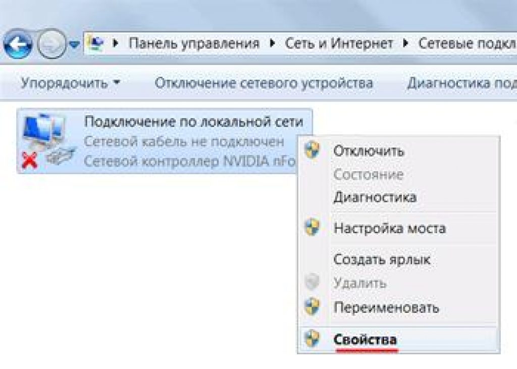
After this we select "LAN connection" and right-click. And then we click on .
After everything has been done, click on and then click on .
For the wifi tp-link repeater it is 192.168.1.21, the mask is 255.255.255.0. Having specified all the values, you need to confirm your actions and finish this part of the procedure by pressing the “OK” button.
Following actions:
You can check the connection status by checking the Status list.
If, when refreshing the Channel page, you notice a stable number change, it means that the security characteristics of the data were entered incorrectly.
On the opposite side of the Name area, the name of the router with which the association is being performed will be displayed; the Channel and MAC Address fields must also be filled in.
"Manual" settings
On the icon that appears, check the box next to the “Use the following IP address” section. The IP address must exactly match the address specified by the manufacturer.
For the wifi tp-link repeater it is 192.168.1.21, the mask is 255.255.255.0. Having specified all the values, you need to confirm your actions and finish this part of the procedure by pressing the “OK” button.
Following actions:
1 Now you need to configure the access in the Wi-Fi repeater. To do this, you need to go to your own Internet browser and enter the IP address in the address bar - 192.168.1.254. First find out if the proxy server is enabled in the browser options; it should be turned off.
2 In the personalization window that opens, enter the login admin and password admin. We look through the Wireless list and find the Wireless Settings item. Opposite the Operation Mode line, set the Universal Repeater position. We approve modifications.
3 A list of public networks opens in the Survey list. Select the one you need by pressing the Connect button. Save the option modifications. This is followed by rebooting the device (Reboot).
4 In the Wireless list, select Wireless Security and in the required fields indicate the code and password of the router itself. Please note that if WEP encoding is activated in the TAKE PROFIT-Link router, then Type, WEP Key Format, WEP Key, Key Type - characteristics must match the router options. Otherwise, the TAKE PROFIT-Link repeater will not determine the connection with the network distributor.
You can check the connection status by checking the Status list. If, when refreshing the Channel page, you notice a stable number change, it means that the security characteristics of the data were entered incorrectly.
After checking the accuracy of the security characteristics entered, leave the changes made and reboot the device.
In order to control the process of combining the repeater and router, find the Status list and see if there is a connection.
On the opposite side of the Name area, the name with which the merger is being performed will be displayed; the Channel and MAC Address fields must also be filled in.
In the Traffic Statistics area, you will see a display of changes made to the device settings.
Then press the repeater key at the top in the corner. A list of all public networks will appear. Here you need to select exactly the position with the device whose signal you want to enhance.
Here you can specify your own Wi-Fi repeater or save it with the name given to it by the manufacturer. The final stage: entering your own Wi-Fi password.
Inspecting the connection status
After installing the repeater or router in the repeater system, you need to check how the Wi-Fi repeater functions and how well it picks up the network.
It would be a good idea to check this on all your own devices - tablets, phones - whether they know the network that the repeater distributes, or whether they also continue to connect to the main router (for this it is suggested to specify different names in the options).
In addition, find out whether you have installed a Wi-Fi network repeater for the router in a suitable area, and whether you have achieved your goal of improving the quality of communication.
It is not at all necessary to look for places where the number of sticks changes. Modern method involves downloading one of the specialized applications to the device, which will help control the intensity of signal production.
Keep in mind that if you need to increase the signal extension over a fairly large area, especially if also at different slopes (for example, into a tier and into an adjacent room), then most likely you will need to purchase two repeaters.
Setting up network protection: nuances
You should set the network security parameters by configuring the appropriate characteristics in accordance with which the repeater and WiFi should operate.
To do this, you need to select the Wireless option, and then Wireless Security. Then you need to determine the WPA2-PSK parameter, and also the AES encoding method.
Afterwards, insert a password that matches what is specified in the settings. Then click Save.
Thus, the user’s main goal when installing a repeater is to synchronize the device with the computer to which it is connected and set the appropriate parameters.
Network testing
After setting up the correct device, you should check that the wireless network is working correctly. Therefore, you should select the System Tools setting, then Diagnostic.
After this, you should enter in the IP address area the address that is designated for the router. Then you need to click Start to launch the testing device.
TP-LINK repeater review
First of all, it should be emphasized that the TP-LINK company manufactures special equipment, including repeaters, offering a wide range of different models and options.
If we talk directly about devices of this type, that is, a popular invention among them, it combines these functionality, common to many advanced TP-LINK repeaters, is called the TL-WA850RE.
In particular, the products provided have the main advantages:
- the TL-WA850RE repeater is capable of working as a radio signal amplifier, as a result of which the wireless network has the ability to expand over a significant area;
- the device is small in size, so it does not take up much space, even if there is little free space in the user’s room or office;
- If necessary, it is possible to connect wired devices to the router using the Ethernet port.
The device in question is designed for connection to Wi-Fi routers that have a WPS function, provided that the routers have the appropriate keys.
If such a connection was once implemented, then secondary configuration of the repeater, as a rule, is not necessary.
And if we talk about functionality in terms of using the Ethernet port, then devices such as game consoles, televisions, and also various multimedia devices can be connected to the device.
In this case, a device connected to the cable can, using the potential of the repeater, in turn become a component of the wireless infrastructure.
The repeater is equipped with a considerable number of LED indicators, with the help of which it is possible, first of all, to establish the location of the device.
Conclusion
So we “analyzed” the repeater, figured out what it is, what appearance, details of installation and settings, and also found out the nuances in location, quantity under certain conditions of the location of the room.
The most significant convenience that this device provides is not its functionality, but rather the availability of settings.
As a rule, in order to set up a device, you only need to enter the name, where to connect and how - and this is absolutely enough, the rest is created directly by the wifi repeater.
Among other things, we decided whether a Wi-Fi repeater is needed if there are already two routers, and how to rationally position them in relation to each other, taking into account the characteristics of the territory where there should be a good signal.
Increasing signal level
Increasing the comfort of working on the network
Difficulty setting up
Material costs


Repeaters are devices that amplify electrical signals and ensure that the shape and amplitude of the signal is preserved when transmitting it over long distances. They are described by the link layer protocols of the OSI model and can unite networks that differ in protocols only at the physical level (with the same protocols at the link and higher levels) and only perform regeneration of data packets, thereby ensuring the electrical independence of the coupled networks and protecting signals from interference. The use of repeaters allows you to expand the length of one network by combining several network segments into a single whole. When installing a repeater, a physical break in the communication line is created, while the signal is received on one side, regenerated and sent to the other part of the communication line.
30. Bridges, types of bridges.
Bridges are devices that connect two similar networks. Their task is to transmit data packets from one network to another and vice versa. Described by OSI network layer protocols. They regulate traffic between networks that use the same data transfer protocols at the network and higher levels, filtering information packets in accordance with recipient addresses. A bridge can connect networks of different topologies, but running the same type of network operating systems. Networks connected by bridges become one network and have one network address.
Bridges can be local or remote. Local networks connect networks located in a limited area within an existing system. Remote networks connect geographically separated networks using communication channels and modems.
Local bridges are divided into internal and external. Internal ones are located on one PC and combine the function of a bridge with the function of a subscriber computer. External ones involve the use of a separate PC with special software for bridge functions.
There are several types of bridges:
Transparent bridges;
Source-routing bridges;
Broadcasting bridges;
Encapsulating.
Transparent bridge.
Transparent bridges independently build a special address table, based on which you can decide whether an incoming frame needs to be transmitted to some other segment or not. The transparent bridge algorithm is independent of the local network technology in which the bridge is installed. A transparent bridge builds its address table by passively observing the traffic flowing on the segments connected to its ports. In this case, the bridge takes into account the addresses of the sources of data frames arriving at the bridge ports. Based on the address of the frame source, the bridge concludes that this node belongs to one or another network segment. Let's look at the process of automatically creating a bridge address table and using it using the example of a simple network shown in the figure.
Operating principle of a transparent bridge
A bridge connects two logical segments. Segment 1 consists of computers connected using one piece of coaxial cable to port 1 of the bridge, and segment 2 consists of computers connected using another piece of coaxial cable to port 2 of the bridge. Each bridge port operates as the end node of its segment with one exception - the bridge port does not have its own MAC address. The bridge port operates in the so-called illegible packet capture mode, when all packets arriving on the port are stored in buffer memory. Since all packets are written to the buffer, the bridge does not need a port address.
In its initial state, the bridge knows nothing about which computers with which MAC addresses are connected to each of its ports. Therefore, in this case, the bridge simply forwards any captured and buffered frame to all its ports except the one from which the frame was received. In our example, the bridge only has two ports, so it transmits frames from port 1 to port 2, and vice versa. Simultaneously with the transmission of the frame to all ports, the bridge examines the source address of the frame and makes a new entry about its ownership in its address table, which is also called the filtering or routing table. For example, having received 1 frame from computer 1 on its port, the bridge makes the first entry in its address table: MAC - address 1 - port 1. After the bridge has passed the training stage, it can work more efficiently. When receiving a frame directed, for example, from computer 1 to computer 3, it looks through the address table to see if its addresses match the destination address 3. Since such a record exists, the bridge performs the second stage of table analysis - checks whether there are computers with source addresses ( in our case, this is address 1) and the destination address (address 3) in the same segment. Since in our example they are in different segments, then the bridge performs the operation promotion frame - transmits a frame to another port, having previously gained access to another segment. If it turned out that the computers belonged to the same segment, then the frame would simply be deleted from the buffer and work with it would end there. This operation is called filtering . If the destination address is unknown, then the bridge transmits the frame to all its ports except the frame source port, as at the initial stage of the learning process. The bridge's learning process never ends.
Source-routing bridges.
Source routing bridges (SR bridges) are used to connect Token Rings and FDDI rings, although transparent bridges can also be used for the same purposes. Source routing is based on the fact that the sending station places in the frame sent to another ring all the address information about the intermediate bridges and rings that the frame must pass through before getting into the ring to which the receiving station is connected. There is no real routing in the strict sense of the term here, since bridges and stations still use only MAC layer information to transmit data frames, and the network layer headers for bridges of this type still remain an indistinguishable part of the frame data field.
The network consists of three rings connected by three bridges. To set a route, rings and bridges have identifiers. SR bridges do not build an address table, but when moving frames, they use the information available in the corresponding fields of the data frame.

When receiving each packet, the SR bridge only needs to look at the routing information field to see if it contains its identifier. And if it is present there and is accompanied by the identifier of the ring that is connected to this bridge, then in this case the bridge copies the incoming frame to the specified ring. Otherwise, the frame is not copied to another ring. In any case, the original copy of the frame is returned along the source ring to the sending station, with notification that the frame was received by the destination station (in this case, bridged to another ring).
Advantages: More rational routes, simpler and cheaper (no need to build filtering tables), higher speed (no need to look through filtering tables).
Disadvantages: More expensive network adapters that take part in routing, the network is opaque (rings have numbers), traffic increases due to broadcast packets.
The presence of two possible bridging algorithms - source-based and transparent - creates difficulties for building complex Token Ring networks. Source-operated bridges cannot support segments designed to operate in transparent mode, and vice versa. Until some time, this problem was solved in two ways. One approach was to use either only source routing or only transparent bridges on all segments. Another way was to install routers. Today there is a third solution. It is based on a standard that allows both bridge technologies to be combined in one device. This standard, called SRT, allows the bridge to operate in any mode. The bridge looks at special flags in the Token Ring frame header and automatically determines which algorithm to apply.
Broadcasting bridges.
This is a special form of transparent bridge for connecting networks with different protocols at the data link and physical layers.

This bridge connects networks by manipulating envelopes coming from the network. The envelopes of Ethernet, Token Ring, and FDDI networks are the same. But the difficulty is that different networks receive packets of different lengths. Because a relay bridge cannot split packets into pieces, each network device must be configured to transmit packets of the same length.
Encapsulating bridges.
These bridges connect networks with the same Ethernet physical layer protocols over a network with different protocols.

Unlike broadcast bridges, encapsulating bridges place the received packets inside another envelope, which is used in the backbone network. Then it transmits it along this highway to other bridges for delivery to its destination.
Bridge operation during transmission from segment A to segment B.
Bridge1, using link and physical layer protocols, reads the destination address from the headers of packets transmitted over segment A. Places all packets addressed to other networks into FDDI network envelopes addressed to all backbone bridges and sends this envelope along the backbone.
Bridge 2, having received the envelope, opens it and compares the destination address with its address database. If the address is not for this network, then the envelope is passed on.
Bridge 3, having received the envelope, opens it and compares the destination address with its address database. Because the destination address is on its network, the bridge takes the packets out of the envelope and sends them to their destination.
Bridge 4 performs the same actions as bridge 2.
Bridge 1 removes the envelope from the FDDI network.
Many manufacturers, and even more so sellers, indicate their communication range on the radio stations they sell, but unfortunately many buyers without specific experience forget that these figures are indicated for ideal conditions, and in real use these figures differ, and unfortunately not for the better. Simply put, if you bought a radio station and the instructions for it indicate that it works at a distance of 5 km, this does not mean at all that you will be able to communicate at a distance of 5 km, although amateur radio band 70 cm is so unique and interesting that the radio range can exceed your expectations very much;).
What to do? How to increase the distance? This is where such an amazing thing as a repeater, or as many people call it “turnip”, comes to the rescue :)
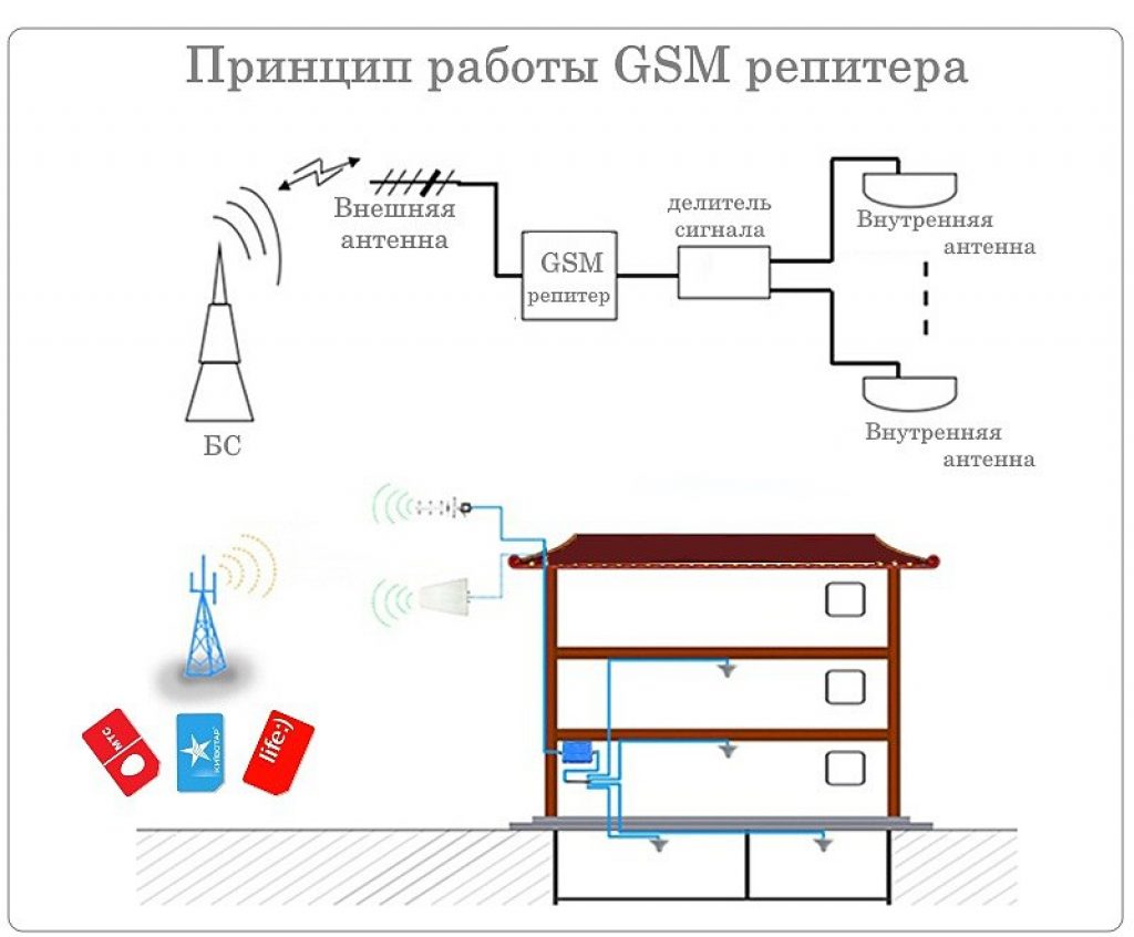
A repeater is a transmitting and receiving radio device that amplifies received signals and transmits them further. The repeater has an antenna (or several antennas), a radio receiver, a radio transmitter and an electrical power source.

The work of the repeater we are interested in can be described using the example of the work of two correspondents located in different parts of the city and not able to communicate directly (in a direct channel), i.e. receive and transmit signals on the same frequency.
Both correspondents' radio stations are tuned to the same frequency, in our case 433.100 megahertz. Correspondent “A” begins transmitting, the radio station automatically* changes the receiving frequency (433.100 MHz) to the transmitting frequency (438.600 MHz), the difference between the receiving and transmitting frequencies in this case is 5.5 MHz, which is called “spacing”. In this case, the spacing is plus 5.5 Megahertz. The sent signal at a frequency of 438.600 MHz is received by the repeater and almost simultaneously transmits this signal at a frequency of 433.100 MHz, which in turn is received by correspondent “B”. The return transmission of correspondent "B" is the same sequence.

Most repeaters are closed to the so-called tone**, in our case it is a tone of 77 hertz. This is done so that third-party signals and interference are not received by the repeater and do not interfere with its operation. This technology is based on the presence in the useful signal of audio tones of a certain frequency that lie outside the modulation frequency range (outside the audibility range), i.e. The repeater is activated only when the specified tone for which it is programmed appears.
P.S. When the overheating protection is activated, in the form of a repeating tone, you must release the transmission and allow the repeater to close.
* for automatic “spacing” of receiving and transmitting frequencies, use the instructions for your radio station; in most cases, this is called “shift” or “RPT” and is adjusted to plus or minus the required frequency shift, in our case 5.5 MHz, i.e. 433.100 + 5.5 MHz = 438.600 MHz.** to turn on the required tone when transmitting a signal, use the instructions for your radio station, in most cases it is called CTCSS (Continuous Tone-Coded Squelch System), in our case CTCSS 77.0.
Good luck with your connection!
Nowadays, the use of repeaters is becoming increasingly widespread, while the area of their application is not only not limited by the professional activities of cellular providers, but is also increasing among citizens who do not have any relationship with the mobile network, i.e. Ordinary subscribers. What is a repeater and what models are there, as well as the scope of implementation.
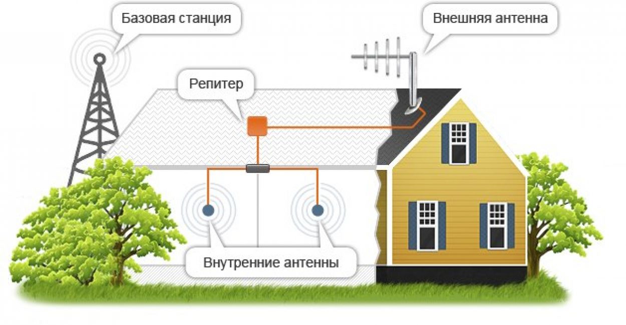
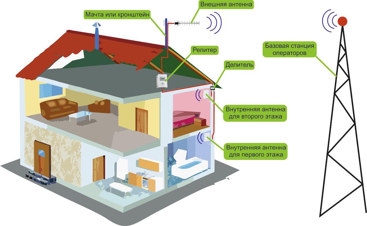
First of all, let us highlight that repeaters are bidirectional cellular amplifiers, which are connected to several antennas simultaneously. With the help of one antenna (donor), the repeater acquires a stable connection with the service station and directly with a cellular telephone or other communication unit. As a result, repeaters work as a means of amplifying both several frequency channels and the frequency spectrum in general. Everything described gives rise to a lot of options for repeaters, the specific operation of which in a separate version has its own characteristics, which you should definitely pay attention to when choosing a mobile amplifier. So, in particular, channels that use time differentiation, where several different channels are formed at the same frequency (take GSM, for example), need to amplify the frequency channel. In the provided option, provided that single-band GSM cellular repeaters are used, a significant improvement in connection reliability can be achieved. A completely opposite method is needed when operating mobile amplifiers in compact office rooms, because here it is necessary to increase the full frequency range, including signals from several providers. Again, in particular, GSM broadcast repeaters designed to work in compact spaces can help.
Consequently, in the epilogue of everything that has been said, let’s announce the important types of repeaters presented at the moment, and briefly analyze the features of each.
The already mentioned GSM repeaters are considered the most popular and fundamental, the main advantage of which is the unlimited transmission length. The current GSM repeater will be able to function according to GSM, DCS, UMTS and other standards.
In addition to this, GSM repeaters are divided by band width into channel and band. Optical repeaters are also used in professional environments. Of course, when using a GSM repeater, you will also need a 3g antenna.
Thus, as we note, at the moment a repeater is simply an indispensable device that allows you to stay in touch.
The history of transistors begins in the middle of the 20th century, when in 1956 three American physicists - D. Bardeen, W. Brattain, V. Shockley - were awarded the Nobel Prize “for research into semiconductors and the discovery of the transistor effect.”
It is sometimes difficult for a radio engineer starting work in his field to understand electronic circuits ah and the purpose of certain of its components. For this, there are certain developments - already invented circuits for connecting transistors and other elements with certain properties, from which various devices can be composed. One of these “building blocks” in the building of electronic circuits is the emitter follower on a transistor.
Transistor connection diagrams
There are three types of inclusion bipolar transistors- with a common base (CB), a common emitter (CE) and a common collector (OC).
The most common connection is (OE), as it gives a large gain in voltage and current. One of the features of this connection is the inversion of the input voltage by 180 0. The disadvantage of the connection is the small input (hundreds of Ohms) and large output (tens of kOhms) resistance.
When an input voltage is applied, the transistor opens and current flows through the base to the emitter, while collector current increases. The emitter current is summed from the base current and collector current: I E = I B + I K
In the collector circuit, across the resistor, a voltage appears that is much greater than the input signal, which leads to an increase in the output voltage, and accordingly, the current.
Turning on the transistor according to the (OB) circuit gives voltage gain and allows you to work with a wider frequency range than the circuit with (OE), therefore it is often used on antenna amplifiers. This circuit makes full use of the transistor's ability to amplify high-frequency signals ( frequency characteristics). The higher the frequency of the amplified signal, the lower the voltage gain. This stage has low input and output resistance.

Turning on the transistor with (OK) gives current amplification and is often used as an adapter between a high-resistance power source and a low-resistance load. Also, this inclusion can be used when matching various cascade circuits; it does not change the polarity of the input signal.

General concepts about repeater
An emitter follower is a current signal amplifier in which the transistor is turned on according to the circuit (OK). The voltage gain of the signal is almost equal to unity, the emitter voltage is equal to the input signal, so the circuit is called an emitter follower. We will consider the operating principle of the device below.
Despite the fact that the emitter follower has a voltage transfer coefficient of unity, it can be classified as an amplifier, since it gives amplification in current, and therefore in power: I E = (β +1) x I B, where I E - emitter current, AND B - base current.
With low resistance, the collector of the transistor is connected to the common bus, and the resistor from which the output voltage is removed is connected to the emitter circuit. The input and output are connected to external circuits using capacitors C 1 and C 2. When the voltage gain is small, the current gain reaches its peak in short circuit output terminals.
Operating principle
Load cascade circuit The repeater is a resistor on the emitter R E. The input signal enters through the first capacitor C 1, and the output signal is removed through the second capacitor C 2.
The emitter voltage follower has a very low input resistance and a large output resistance. With alternating current, when through a transistor p-p-p type a half-wave of positive alternating voltage passes, it opens more strongly and the current increases; with a negative half-wave, the opposite is true. As a result, the day off AC voltage has the same phase with the input and is the voltage feedback. Output voltage directed towards the input and connected in series, so the emitter follower uses serial negative feedback. The output voltage is less than the input voltage by an insignificant amount (base - emitter voltage is about 0.6 V).
How to calculate a circuit

The initial data to make the calculation of the emitter follower are the collector current (IK) and the supply voltage (U VX):
- The emitter voltage (U E) must correspond to: V E = 0.5 x V VX (to ensure maximum swing for the output voltage).
- Now you need to calculate the resistance of the resistor on the emitter: R E = Y E /I K.
- The resistance of the resistor divider is calculated: P 1 -P 2 (we select the resistance so that the current on the divider is approximately 10 times less than the base current): I D = 0.1 x I K / β, where β is the current gain transistor. Resistance P 1 + P 2 = U VX / I D.
- We calculate the base voltage relative to the ground: V B = V E + 0.7.
Distinctive features
The emitter follower has an interesting feature - the collector current depends only on the load resistance and input voltage, and the transistor parameters do not play a significant role. Such circuits are considered to have 100 percent voltage feedback. You don't have to worry about burning the transistor by supplying power to the base without a limiting resistor.
The operation of the emitter follower is based on a high input impedance, which allows you to connect a signal source with a high complex impedance to it (for example, a pickup in a radio). Amplifier
Very often, an emitter follower is used as a power amplifier in the output stages of amplifiers. The main task of such nodes is to transfer a certain power to the load. The most important parameter that is set in amplifier power calculations is the power gain , distortion of signal transmission and efficiency (its increase is necessary due to the consumption of most of the power of the power supply by the output amplifier) . Voltage gain is not a major parameter and usually approaches unity.
There are several ways of operating such an amplifier stage, depending on the location of the operating point on the characteristics graph and, accordingly, with different efficiency and characteristics of the output signal.
Operating modes
In the considered cases of operation of the emitter follower, the collector junction will be reverse biased and the operating mode will depend on the emitter junction:
- In the first case, the emitter junction is shifted in such a way that the transistor does not stably go into saturation mode and the repeater operates on the straight section of the transfer characteristic graph (voltages V K and V E are the same). The maximum output voltage is less than the input voltage. The efficiency is equal to the ratio of the power supplied to the load to the power from the power source, and reaches a maximum (25%) at the highest amplitude of the output voltage. To avoid mismatch between the output and input signals, the amplitude of the output voltage has to be reduced, as a result, the efficiency also decreases. The low efficiency in this operating mode of the repeater is due to the independence of the current passing through the transistor from the supply voltage and the power consumed from the power source is a constant value. In the absence of an input signal, the power dissipated by the transistor is greatest. Therefore, in this mode, the emitter follower is not used as a power amplifier, but rather as a low-distortion signal transmitter.
- Another operating mode of the amplifier stage, in which the bias of the emitter junction brings the operating point of the transistor to the boundary of the turn-off region. If we accept the emitter voltage (U E = 0) and there is no input signal, the emitter junction is reverse biased and the transistor is in the off state. As a result, power consumption is reduced. When a positive half-wave passes from the power source, the transistor is unlocked (the emitter junction opens), and the negative half-wave closes it (there is no output signal). The second case of operation of the amplifier stage solves the problem with increasing Amplifier efficiency, because there is no current on the transistor if there is no supply voltage. But there is a drawback - strong distortion of the output signal.
Push-pull circuit
A push-pull emitter follower allows for current amplification in the positive and negative ranges. To obtain a bipolar output signal, you can use a complementary emitter follower. Basically, push-pull circuit- these are two repeaters, each of which amplifies the signal in the positive or negative half-wave. The circuit consists of two types of bipolar transistors (with p-p-p and p-p-p junctions).

The principle of operation of the complementary circuit
When there is no input power, both transistors are turned off due to the lack of voltage at the emitter junctions. When a half-wave of positive polarity passes, the p-p-n transistor opens; similarly, the passage of a negative half-wave causes opening p-p-p- transistor.
A powerful emitter follower has an efficiency calculation (K = Pi/4 x VOUT / VK), where Vout is the amplitude of the output signal; V K is the voltage at the collector junction.
From the formula it is clear that K increases with increasing amplitude of YOUTH and becomes maximum at YOUTH = YK (K = Pi/4 = 0.785).
This shows that the emitter follower in a complementary circuit has a significantly higher efficiency than a conventional follower.
The property of this circuit is that large (transient) nonlinear distortion. They manifest themselves to a greater extent, the lower the input voltage (VV).
Calculation of a push-pull amplifier
Since we need an emitter follower for power amplification, the initial data to calculate the emitter follower will be: load resistance (RL), load power (LP). To reduce the mismatch between the output and input signals, the supply voltage should be 5 V higher than the output voltage amplitude.
Formulas for calculating the amplifier stage:
- Output voltage: V OUT = square root (2P N R N).
- Power supply voltage: V VX = V E + 5.
- Output current: I E = U E / R N.
- Power taken from the power source: P + + P - = 2/Pi × U E /P N × U K.
- The highest power dissipation on each of the transistors: P 1 = P 2 = U K 2 / Pi 2 R N.
Reduced output voltage distortion
The push-pull emitter follower, the operating principle of which is described above, can be further improved by reducing transient distortions of the output signal in its circuit.
To reduce voltage distortion at the output of the stage, voltages can be applied to the bases of the transistors, shifting the output characteristic.
For bias, diodes or transistors are used that supply a signal to the bases of the repeater's working transistors.
Circuit using diodes

A bias appears at the emitter junctions of transistors T 1 and T 2 due to diodes D 1 and D 2 connected between the bases of the transistors. When the input voltage is zero, the transistors are active. When the voltage polarity is positive, transistor T 2 is turned off, and when the voltage polarity is negative, transistor T 1 is turned off. When the input signal is zero, one of the transistors is active, so the diode circuit gives an output signal characteristic that is very close to linear. Instead of diodes, you can use transistors with shunted collector junctions.
Power amplifier with additional emitter followers
Another circuit that reduces the distortion of the output signal, at the input of which two transistors are connected.

In this circuit, two transistor followers are placed at the input, which bias the emitter junctions of the two output transistors. A significant advantage of such inclusion will be the increased resistance at the input of the cascade. The emitter currents of the input and base currents of the output transistors are set by the first two resistors. The second two resistors are included in the feedback circuit for the output transistors.
This connection option is a buffer amplifier with unity voltage gain.
Composite transistors
Now transistors are produced in the form of a separate cascade of two transistors in one package (Darlington circuit). They are used in microcircuits in amplifiers with discrete components. When replacing a conventional transistor with a composite one, the input resistance of the circuit increases and the output resistance decreases.

